Tuesday, May 31, 2022

Fitting the floor

 A few days ago my partner and I had a new kiln controller installed, and I got chatting with the engineer about my projects, and he offered me some scrap metal left over from working on large installations. He reckoned I was doing him a favour emptying his van! Generous chap! As a result, I got all the aluminium treadplate I need! From it I made the floor of my Bédélia, which I fitted today. It sits of brackets which I plug-welded earlier. 

It took a fair bit of fettling because I had to file away at the edge to fit it round the supporting brackets. 


I drilled though the brackets beneath. Then bolted the floor down. This is temporary, as the nuts will eventually be welded captive under the car. Not sure which fixings to use yet, but spring washers will be used. Will probably use button headed hex fittings.


I supported the kart on wood and sat on the floor, now taut, and it held fine.


.


Aluminium rear

The rear of my "chassis" is not load-bearing, as the engine supporting part of the frame is in-board. So the rear portion of what will originally have been the chassis is far lighter, as I have made it in aluminium. This unequal aluminium comes in at 1kg per metre, as compared to the box section steel which is 2.2kg/m.


I gusseted it roughly every 10mm along the top, narrower surface, then bent it gently over a wooden former to make the base of the tail section, which will be held in place riveted steel out-riggers.

I have never welded aluminium. The trouble with the stuff is that, being soft, it tends to be distorted by the rollers which propel it out the end of a welder, and because it is very soft, is inclined to be slowed inside the welder liner through friction....and becomes snarled up into what is called a birds' nest. It is a bit of a nightmare. To get around this, the spool-gun was invented. This reduces the length of journey the al wire makes from the reel to the tip of the welder, by putting the spool at the back of the hand-held gun. But there is a problem, my welder isn't compatible with them (unless you get a universal spool gun costing about £600!) The alternative is to put a more slippery silicone liner inside the welding gun, but my welder's roller mechanism cannot take v-shaped rollers for pushing the wire, so that it is inclined to birds'nest at the welder end.

Bugger!

Either I need to get a whole new system or get a friend to weld the thing for me. Of course, I'd rather do this myself, but my friend may the best option.

Mick Broom of Hesketh Motorcycles gives his advice


I have been talking to Mick Broom, Chief Development Engineer at Hesketh Motorcycles, who I know through flying. We have mutual friends and his son David was my ex-girlfriend's flying instructor and is one-time World Champion microlighter.

Anyway, Mick has been designing and building motorcycles (including three wheelers and sidecars) since 1979, so there can be almost nothing he doesn't know about things like camber, caster, Ackerman, trail and suspension systems, and he has given me some pointers.

One thing he does recommend is making my trail adjustable so that I can find the optimum distance between my axle and the centre of turn, which trails behind the axle (at the centre of the rising block). He also suggests I build the car and suspend it with aircraft spec bungees first. Then he has advised me on how to weigh the car's axle loads for working out springing, and that each spring should be 2/3 unloaded when stationary.

Wednesday, May 25, 2022

Front suspension - how do you know what spring to get?

 Yesterday I ordered my steel plate for my front suspension supports (those protruding from chassis at the nose) and my tube for constructing the rigid members.

The front axle will be mounted on a box which will sit between two springs;  a large one above and a smaller one below. This type of suspension, most commonly seen on Morgans, is called a sliding pillar, and I have talked about this before.

The sliding pillar is at the nose of the car and either you can think of the front axle sliding up and down it (when the wheels go over bumps), or you can think of it as being the car that is sliding up and down the pillar, whether the car is in motion or not. 

At the start of the project I'd thought that I'd have sliding pillars at the ends of my axles, with my central spring being only a dummy one, to retain the aesthetics of the car, and for that I had taken the advice of David Dupaquier, who has applied these very successfully, and also Rhys Nolan who has also taken David's advice and has been experimenting with them. 

I have asked Springmasters how they would go about working out what springs I'd need. At present I think that for this "O" Level maths failure it would be safest to go with a simplistic notion of taking a spring capable of accepting the load equivalent to my weight and the car's....pivoting on the back wheels, which intuitively tells me, straight away, that it isn't as simple as just the all-up-weight...then trying that out to start with, then trying softer or stronger from there?

What would you do?

Monday, May 23, 2022

"Look at that, Bill; copying us!"


Recently, I have done a lot of research in old cyclecar magazines. Here's a treat from The Cyclecar, December 1912, obliquely referencing the Bédélia's steering, as well as the tandem seating and the car's diminutive scale.


.

Friday, May 6, 2022

drive set-up

 The last couple of evenings I have been playing with my drive set-up and the best news is that I have found a set-up which doesn't clash with other parts, so that I don't have to grind any webs off. I tried to set my TAV pointing down to 4 o'clock, but that means either that my engine needs to be higher than my chassis rails or that my TAV will be closer to the ground. I have tried 1 o'clock, but that means that the shaft bearing housing gets in the way (though taking the tank off to accommodate it seems a good idea anyway - more about this later). Then I tried 12 o'clock - and that was just right! (bit like the Three Bears!)


1 o'clock

12 o'clock


The sloping board represents the seat-back, rear bulkhead. 
Removing the tank improved clearance for this


The only concern here is the exhaust manifold, which puts the exhaust in line with the top of the chain-run. I have removed the exhaust, which I will be replacing anyway, and will be making an exhaust which goes through the middle of the chain-run, keeping it well clear, but also making the bend less extreme for a smooth flow of gas.


Fortunately, a friend has a pipe bender. 😏


Wednesday, May 4, 2022

Happy Torquey Torquey, Happy Torque


A new consignment of Comet Torq-A-Verter torque converters has just cleared customs and, having asked Gemini's Chris Merriman to reserve me one, I am now its proud owner. I had hoped to buy a cheap, generic one, but as those have been out of stock too, and as the more expensive ones were the first available, I decided to treat myself to the added quality.

When I started playing with it yesterday, I realised that the supplied 5/16th mounting bolts weren't going to fit my engine, a Honda clone made by Lifan, which is metric, but as I didn't know for sure what thread my holes had, I took the entire engine with me to Suffolk Fasteners, today, and was served by Emma Digby, the daughter of the owner, Damon, who I used to fence with and who has supplied parts for various of my projects (my Austin 101 restoration, my gyrocopter rebuild, and my Chaser microlight build etc).

Emma is incredibly knowledgeable. Another customer reckoned she'd know the fixing I wanted just by glancing at the engine, and wasn't too far off the mark. We tried M8 fines, found that they turned a couple of times then jammed, so tried a standard thread, and those worked perfectly. If you are local, or even if you need to source fixings online, you really must support Suffolk Fasteners, because it is so seldom that you can get one to one service from experts and be charged for one single bolt, if one is all you need.

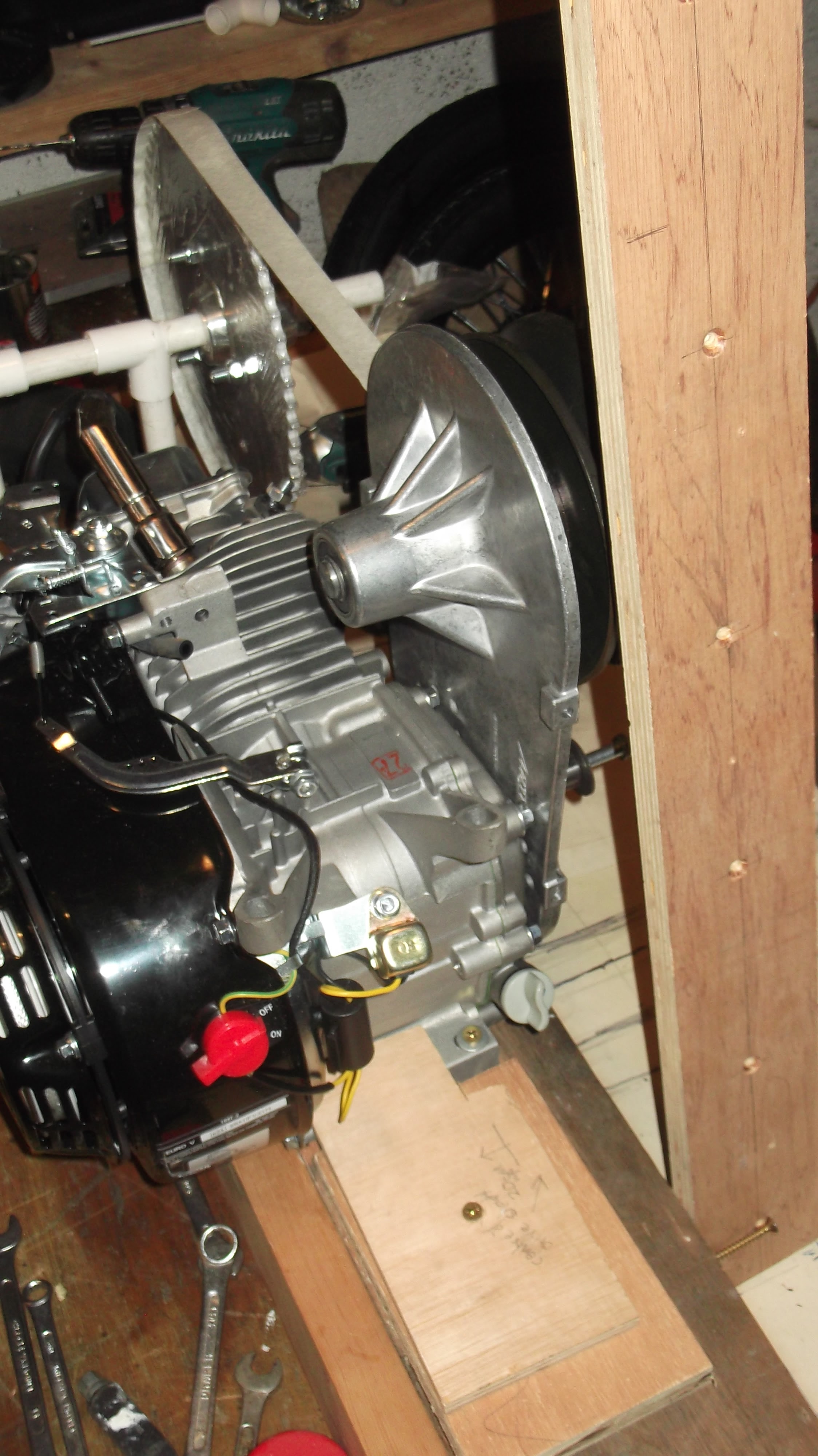
This evening I have been playing with my Lifan engine and trying different mounting arrangements for my torque converter. In what may be the best position for it, one of the strengthening webs (or vanes?) clashes with the oil filler metal, so I plan to grind some of it away. I have seen this done on some YouTube videos of torque converter fitting, so hopefully it isn't too badly frowned upon???


I am going to be replacing the exhaust and also moving the petrol tank, so I took these off and explored the engine generally, and comparing the arrangement with my drawings to see if it is all going to line up with the rear axle etc, and its driven plate-wheel assembly. 

wiring the cockpit leading edge

The shape of the front dash on the rear scuttle is replicated on the front dash of the front scuttle on the original, so I made a template u...