Saturday, December 31, 2022

Pitch perfect

One of the things I really love about building this cyclekart is that I learn about things which I start out knowing nothing about at all, and today it is the naming of the parts of my main drive chain. And for that I consulted a site recommended by Stefan Nahajski, the Chair of Cyclekarts GB: the Cut Price Racing Guide.


picture from Renold.com

picture from hammerinhandcycles.com

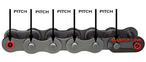
This afternoon I measured the circuit my chain will travel round - when stretched around the driving and driven sprocket - in mm. Then, you just divide this by the pitch of your chain, which in the case of my 420H chain will be 12.7mm and that gives a total number of 92 links, which is what I need to order, bearing in mind that one of them will be a joining link.

Thursday, December 29, 2022

Quick reminder of where this project started

Follow these links:

The concept car 

The mocking up

A chance to see a real Bédélia in action

The faux driver: Monsieur Bourbeau

My work-in-progress on its first outing


Drop-in engine frame

 I have constructed an engine frame which can be pulled out of the engine bay with the engine mounted on it. This makes it possible to keep the engine alignment if ever the engine needs work and access is tight.


engine bay with brackets to hold blue frame

blue frame dropped in 

The engine plate, which is welded to the frame, is slotted so that the engine can be slid back in it, if ever I need to take up slack in the chain.

To brace the engine against sliding towards the drive sprocket (and to assist with alignment) I have welded some nuts at the rear of the frame, so that tightening bolts can bear against the engine base. This last innovation is not my own. Another cyclekarter shared the idea on Facebook recently.

align and brace

alignment checked

engine in


Tuesday, December 20, 2022

skates

An algorithm read my mind and offered me these three wheeled casters. I got some and made skates for slipping under my kart so that it can be moved around easily, as I have little room to work in.


Monday, November 28, 2022

adapting steering box and fitting thrust bearing


Thrust bearings come in inconvenient sizes, for my purposes anyway. The closest size was far too tight, the next size up allowed too much slop. So, to take up the slop I made a bushing, but without a lathe (as I don't have such a thing). I cut off some steel tube, slit it and widened it, made a platform out of a slip of box section (to accommodate the weld connecting the collar to the box), fitted that round the collar (which slides up and down and round the pillar), allowing room for the slit tube, then after hours of grinding and filing, fitted the tube around the collar and inside the raised platform, welded it in place, plug welded the platform to the box and fitted the bearing sandwich with room to move but minimal slop, and made a sheet steel super-washer to sit the spring base on.

All told, it works well.


The raised platform absorbs the weld fillets so that the spring will sit on a turntable which is flat.
Ready for the top bearing washer and the spring base washer. Then the spring.


Monday, November 21, 2022

buck

I have been working on my buck. It is so frustrating. You do a fabulously accurate, dimensioned drawing, then as soon as you start cutting you get all sorts of errors arising from blade thickness, material thickness, etc, and a fine plan ends up looking really dreadful. But at the end of the day, this is just something to lay my metalwork over to understand where I need to stretch or shrink the aluminium to make the cowling. You also need to appreciate that the cowling will be about a centimeter shallower - when the base is removed. 

 have needed to make it slightly higher than the original, to give my hands room to move on the top of the steering-wheel, and you need to appreciate that the steering-wheel, which I am hiding under the cowling, didn't exist at all in the original.

As it stands, the buck covers more of the cockpit than it will in the end because it will have a cut-away which slopes forward on each side.


sliding shrouds on spring

 I might even take the opportunity to make a sliding spring shroud like the original, with the lower shroud (the inner of the two) attached to the large washer and with the upper, outer shroud sliding down over the top of it.


Front bearings set-up

Chris sketched what he had in mind, an extra large washer to distribute the weight of the spring, with the thrust bearing and its washers ranged with a sliding fit around the pillar, though in this case, not the pillar tube but the collar at the bottom. (You will remember I used a collar attached to the top of the steering box to act as a rotating slide.)


Sunday, November 20, 2022

body buck profiles

My cockpit has a rounded cowling, which I will have to hammer-form and wheel on the wheeling machine. For this I need a buck, which will be something to lay my formwork over to see if it is getting close, and to decide where I need to stretch the metal, etc. This evening I have been working out the profiles with reference to photos of old Bédélias, but also in order to fit my own particular cockpit. In particular I want to cover my steering wheel to create the illusion that the car is being driven by the back seat driver, M. Borbeau.

Incidentally, the trick here is to design only half of the profile (front elevation), then use it as a template for the other half. That gives a symmetrical profile, which is hard to achieve free-hand..


Thrust bearings


I reached out on the Cyclekart UK forum and Chris Brown came back with the solution. I need needle roller thrust washers sandwiched between washers between the spring's bottom and the steering box. I don't think I need a bearing at the top of the spring, as this will not then be rotating. 

I need to get bearings where the internal diameter is as close as possible (bigger than) the diameter of the sliding pillar, which is 20mm, and wide enough that its washers (with the same ID) sit beneath the spring. So far, the closest I have seen is a 20/35, but ideally, I need a bigger set - if needs be, with a bush to take up slack in the internal diameter.

This is an exciting development, so big thanks to Chris. The bearings are capable of turning even under a static load/force of more than 50NM, which is equal to 5 tonnes! Is that really possible? Its static load is 14 NM, or just over a tonne! Such numbers make me wonder if I got this all wrong!

Anyway, these bearings should mean smoother running steering, despite the force of the all-up-weight on the spring, which in turn is standing on the steering box.

Saturday, November 19, 2022

new spring fitted - progress

The great news is that once everything settles, with me in the car, it is more or less level using a monoshock spring! Lucy and I both noticed the car dip about 1/2", but when measured front and back the rails seemed to be the same distance from the ground at the extremes. There is a discrepancy in the middle, which is a bit odd, but may be due to changes in the section between steel and aluminium. If it isn't the case that the new spring has solved the problem, shims should correct any error. I may just have to live with it, if this can't be so. Still, it IS encouraging progress.

My fundamental error was in not realising that the driver of the original Bedelia was more of a counterweight to the rest of the car, being over the rear axle, even with the engine at the very front. Mine will be lot less skippy at the nose, which is good, but it does mean that the weight is further forwards, generally, so that the spring has to work harder if the car is to be level.


With the new spring being very firm -pushing up to the top of the nose structure and down to the front axle-, there is a lot of friction at these two points, making steering a lot harder. I think I may need some taper bearings, and to treat this a little like the headstock of a motorcycle. I wondered if I could get away with one bearing race at the top of the spring?

Thursday, November 17, 2022

mono-shock

This one was Jim Rawnsley's idea: a mono-shock spring for my front suspension. My previous spring, one of a pair for a motorcycle, was not stiff enough. Meanwhile, having sent my numbers off to a spring specialist, I was told that they didn't have anything suitable, and they would have to do a custom job which would start at £150. So rather than spend a fortune, I thought, ok, it may not be the proper thing to do, but I will just try whatever is available - and available second hand. So, this one today is a spring off a DT174MX motorcycle. In theory, it is about twice the spring the previous one was, except that I am not inserting an inner spring, so should be extra without being excessive. In theory.

Reading that back, I am not sure it makes lots of sense, but never mind because nobody is reading this anyway.😁


Monday, October 31, 2022

horizontal weighing

 I just made a lifting element and put it between the scales and the nose, so that I could weigh the car with the chassis horizontal - parallel to the ground, and I got in. Total weight, with legs forward this time (I think I forgot last time), was 64Kg (60 with legs pulled up). That means that 10Kg have shifted backwards by lifting the nose. Interesting.

There will be a few kilo's front and back, but I think I need to be looking for a spring which will hold a stationary load of about 66Kg (145lbs)

Sunday, October 30, 2022

the lever-weight enigma


Today I tried fitting the nose with the lighter spring augmenting the heavier one by rotating it spirally down inside it, and this improved things. 


It meant that the car stood largely horizontally, but unfortunately it sank forward about 1/2" with me sitting in it. So I took the front axle off and weighed the car at the front to work out what kind of work the ideal spring is going to have to be able to do.

My weight is around 84Kg and the kart is about 70Kg (with the 17Kg engine in front of the back axle), so our combined weight is about 150Kg. How, then, can it be that with me sitting in the kart and with scales under the nose of the kart (front axle removed), the total that the front spring must hold up (without compressing, until it is bounced) is only 68Kg?

I know this is about levers and moments and all that jazz, but I still find it a mystery. Can anyone explain?


Tuesday, October 25, 2022

designing removable back section around running gear


motorcycle spring

 On Jim Tanner's advice, I obtained a rear motorcycle spring and today fitted it in the kart's sliding pillar arrangement, but it is still not quite right. My car front is down a 1/2 inch at the front. I reckon I will slide the previous spring down the inside after work tomorrow, then see where we are.


Sunday, October 16, 2022

Front suspension progress

Two springs make up the front suspension, an upper one and a lower one. But my range of springs is limited. I probably ought to work out the right spring mathematically, by weighing the car (with me in it) and by putting scales at the nose, using the rear axle as a pivot. But I just took a too long spring, compressed it and tried it. It isn't strong enough. Without me in the car it is nose-down. But it feels like real progress.


Sunday, October 9, 2022

Photo by Robina Elizabeth Fry

 I like the effect that Robina Elizabeth Fry gets with her photos, using Photoshop.  This one looks a little like a painting.


Here are pictures from Sywell. Look at my friends' amazing cyclekarts


Of course, I couldn't drive with them this time. But can't wait to join them.

wiring the cockpit leading edge

The shape of the front dash on the rear scuttle is replicated on the front dash of the front scuttle on the original, so I made a template u...