Thursday, March 31, 2022

Sliding Pillar Suspension - discreet and elegant


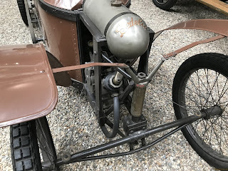
The Bédélia, like the Automobilette, which was based on it (above), had a very unusual front axle arrangement, with two pivots, one which allowed it to pass, almost independently, over obstacles, and the other, which turned the entire axle for steering, with the turn activated with cables - a system called wire and bobbin. I can imagine the amount of tyre scuff! But apparently the vehicle's length meant that actually it was a very stable system, and as the car was successful in pre-WW1 racing, presumably it worked well. 

Suspension was at the centre of the axle, with the bottom bracket flexing like a swinging arm, and the upper stays being rigid (or so I am guessing, because frankly, there is little information that I have been able to find).


However, keen as I am to build a faithful caricature of the original, I think I will be asking for trouble if I replicate that complicated articulating system, and as my wheelbase is going to be a lot shorter, I shall avoid a lot of heartache by making my steering more conventional by following the Ackerman rules, so that the wheels steer at the ends of the cross tube, on stub axles.

I was going to have quarter elliptical suspension springs protruding from the chassis, but this was going to make the car very unlike its original at the nose, and that bothered me... until I saw some experiments that Rhys Nolan has been doing, inspired by the suspension on a very successful cyclekart built in the USA by Dave Dupaquier, the Maserati 250F.

Rhys' experiment is designed to see if Dupaquier's design can be done without welding

Ordinarily on cyclekarts, the axle is suspended (rides on springs) with the wheel mounted on a stub axle, which rotates inside a yoke on the ends of the axle.

typical arrangement

But what is particularly clever in Rhys' version is that the yoke has been extended to accommodate two springs, the strongest on top, against which the car bounces, with the lower spring cushioning the unloading of the top spring. The kingpin, in this case an M16 bolt, passes through the spindle of the stub axle, so that the whole caboodle rides up and down it, providing the car with independent suspension at the front. The lower spring is something that Rhys has added to the system which Dave Dupaquier devised.

Dave's idea reverses the spindle yoke arrangement, putting the C-bracket/yoke at the end of the axle and the spindle tube on the end of the spindle, as on a go-kart stub axle, but with the centre of the spindle tube rising and descending on the kingpin. This is not a new idea but it is very seldom seen. Anyone with experience of Morgans will recognise it as a sliding pillar suspension system, but it was first seen in 1898, with this a 1908 version on a Sizaire-Naudin. In this case the head of the kingpin butted the end of a transverse leaf spring. 


Sizaire-Naudin of 1908 (Wiki: Buch-t)

                                                         
Dave Dupaquier's gorgeous Maserati 250F
                                     
Dave's elegantly executed sliding pillar suspension


What makes this so exciting for me is that it provides a very simple, elegant and discreet arrangement which will make it possible to put Ackerman steering and suspension on my Bédélia cyclekart without severely compromising its aesthetics. 

I have asked Gemini Karts if they'd be able to re-arrange their axle components like this. They are willing to, once they are less busy, which makes me wonder if I should try to do so myself, for now anyway.


So this evening I have been in the workshop fabricating a prototype using rectangular section steel tube, cut longitudinally, with top and bottom of the yoke right-angles cut from the same section, cut cross-ways. Both ends will be chain-drilled and welded, with M16 bolts for kingpins and M16 washers to tidy the holes.

Three bits, rough-cut + top spring


A work in progress.


Sunday, March 27, 2022

Removing studs from GoKart hubs


Part of the kit for attaching my back wheels to my rear axle are these very nice anodised aluminium hubs, which I was first shown by Jim Tanner, an engineer and celebrated cyclekart builder, who has come up with some adapter plates which fit these three-point hubs to the four screw arrangement on the Pit Bike wheels . The hubs come with studs fixed in them, but these need removing, to be replaced with cap head screws. Removing them takes a bit of technique. They are tightly screwed in with something like locktite, which resists their removal.

I didn't want to gnarl up my hubs in a vice, so I clamped them with wood screwed to a bench, providing some leverage so that the hubs wouldn't turn.


I then screwed two nuts on to a stud and locked them in place by tightening them against each other.


This method provides something for a spanner to work against so that 
the stud will screw out of the hub. 

To soften the locktite-like-stuff, I applied heat with a hot-air gun. This was only unnecessary with one of the studs, and did the trick with all the others. I went gently with this because it is difficult to know how much heat will be needed and you don't want to affect the component.


There's a very satisfying feeling as the screw starts to yield then finally comes out!


Saturday, March 26, 2022

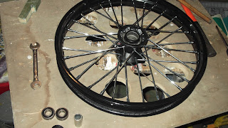
Extracting seals and bearings from a wheel

With original Honda wheels of this size being increasingly scarce and with Chinese clones of either dubious or unreliable quality, 17" Pit Bike wheels are an acceptable and popular substitute. Pit Bikes are dirt bikes or motocross motorbikes for kids, and for me, the fact that they are designed for relatively rough use is reassuring, compared to wheels designed for commuter bikes. Mine came with solid spokes with a reassuring ring to them. You get some really decent quality for an incredibly low cost, especially compared to used Hondas and their clones; £18 each, (incl postage) as compared to around £50+ a piece for the alternative.

The PB wheels come with 6202-2RS bearings, which have an internal diameter of 15mm, which is too small to fit them (at the front) on to stub axles, which are 17mm. So I shall be replacing them with 6003-2RS, which have the same outside diameter of 35mm, but the larger internal one. 

Friends in the hobby are presumably so experienced with all this that when describing how to replace the bearings, they just blithely say "knock them out". So with our poached eggs on toast this lunchtime, Lucy and I watched a few YouTube videos on how to extract bearings and less that ten minutes after lunch, I returned from my workshop with bearings and spacer from the first wheel in hand, a broad grin and a grand feeling of satisfaction. You really can learn almost anything from YouTube. 


1. Remove rubber seal


2. This reveals the bearing. You can just see a slight ledge down the middle of the shaft.
This provides a tiny land you can knock against to force the far bearing and spacer out. Alternate opposite sides (12 o'clock, then 6; then 3 o'clock, then 9; repeat). This stops the bearing from becoming jammed, but is more of an issue when removing old, and rusty bearings. (This also something to keep in mind when putting new bearings in).


"Look mum, no hands!"


Ready to receive new bearings (front) or oilite bushes (rear)


articulated steering


p.s. decided not to use the following, now


Last year I crashed a gyrocopter and my leg got pretty badly bashed up when the cockpit folded in on me. That has made me very keen to have a very un-cluttered cockpit in my car, and because the foot-well is already going to be very tight, I have decided to design my steering shaft so that it is clear of my legs and follows the lines of the hood. But that means articulating it with universal joints, which I have been playing with.

I ought to do a short video for this to show the transfer of rotation. We all know it works in theory, of course. But I rigged this up to confirm it - and it has been quite fun and reassuring.


The sketch shows the shaft following the internal contours of the cockpit. I plan to put in one more UJ, to soften the line and end up in line with the shock absorber at the front.

Making a mockery


I made 23" paper wheels and taped them to a wall (touching the floor), with their centres 66" apart, then using an old, school Epson projector, projected an image of a Bédélia and gradually adjusted its size until the cockpit fitted my outline with the wheels as close as possible to the spread of mine.

The Bédélia was a long, narrow car, with wheels at the corners. It cannot have a 66" (or even 72") wheelbase without quite a lot of compromise, which meant that I played with several versions by over-laying in "Paint" and also simply cutting and sticking the old fashioned way. And I projected my results in the same way.

(I really should find a way to flick-book-animate these, as the subtle changes look great taken in quick succession. Get in touch if you know how that's done)


I made adjustments by over-laying alternatives, moved things around, scribbled changes and annotations, etc.

Once I had established some cockpit measurements and had some idea of where chassis rails should be, I made a largely flat-faced 3D mockup in correx and cardboard


The engine of the original Bédélias was in the front, but as my engine (in common with most cyclekarts) is in the back, I have the opportunity to turn that space into a rather snug foot-well. However, being an already snug car, as it was, this will not be a very much smaller compartment than it originally was. Having my feet in there means that my main mass can be well forward of my rear axle, which will be good for stability. I have lowered the base so that I will be sitting 4" from the ground.

But the downside to not reducing the size of this box, and of not very greatly altering the size of the cockpit is that there is a danger of the original proportions being badly distorted. But I have played with this a lot and am fairly confident  that it can be made to work.


What and why?

 By way of brief explanation:

I am fascinated by the first ever cyclecar - a car built on motorcycle technology, the Bédélia, a French design from 1910. I am also crazy about cyclekarts, which are very essentially go-karts built to look like racing cars of the inter-war years - though these are not replicas but tributes, which are "inspired by" the original. Cyclekarts are single-seaters, powered by 200cc utility engines, driving on 17" Honda 90 wheels with a wheelbase as close to 66" as possible, which is what makes it particularly challenging. And everyone involved has to build their own.

I am therefore building a cyclekart inspired by a Bédélia.


Since this sketch, I have abandoned the idea of foot steering 
and now plan to have a series of UJs so that my shaft can avoid the foot-well.

Since drawing this design, I have re-shunted stuff so that the back wheels are now at the back of the car, so that while it be a lot shorter than the original, it will still have wheels in the corners.


Compressor for sale

 email me on tinworm63@gmail.com